
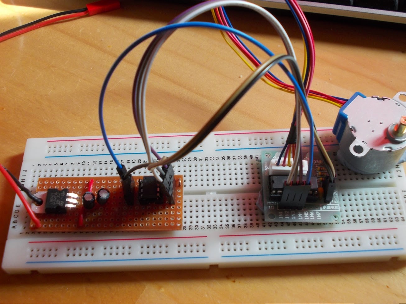
The two wires coming out of the left side of the board connect it to the power supply (in this case a bench power supply @ 12V); the wires at the right power the stepper driver and provide the pulses to drive the motor:
The ATTiny85 was programmed by piggy-backing on an Uno, which I have to say is very easy, although I eventually decided to make a programmer shield for the Uno so that you can just plug in the ATTiny85 directly into the shield and program it without needing to connect any wires. (Note: the stepper motor above was not used for Tim’s blind project – just for testing. He used much larger motors for his project).
I made three of these boards and Tim used them in his project. We also had to fabricate 4 new adapters for the blinds. One of the blinds was quite big, and even though Tim used a higher torque motor, the weight of the canvas on the blind pulled the blind down against the force of the motor. This was a bit of a problem, and the solution seemed to be in gearing the motor in some way to increase the torque. After a little thought, I came up with this:
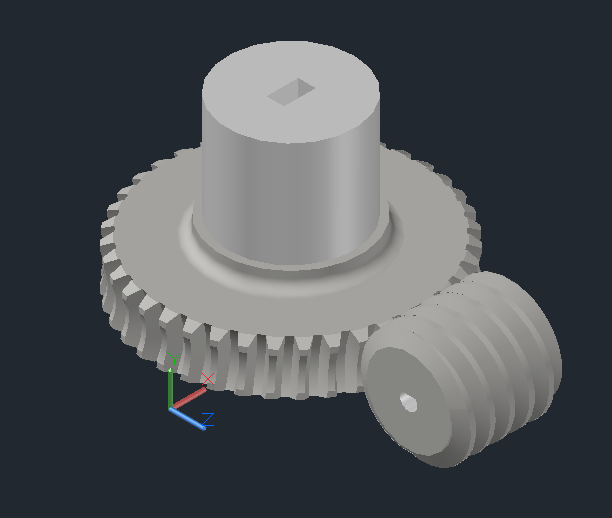
A worm gear that would increase the torque by an order of magnitude, and stop the blind from pulling down. Here’s the work in progress as we tested out the motor driver (and killed it, though fortunately had a spare) and programmed the microcontroller for speed and the correct number of rotations:

We used the Uno for this particular arrangement after having blown the original driver. The motor was later attached to the frame using the bracket that we fabricated with the Cube:
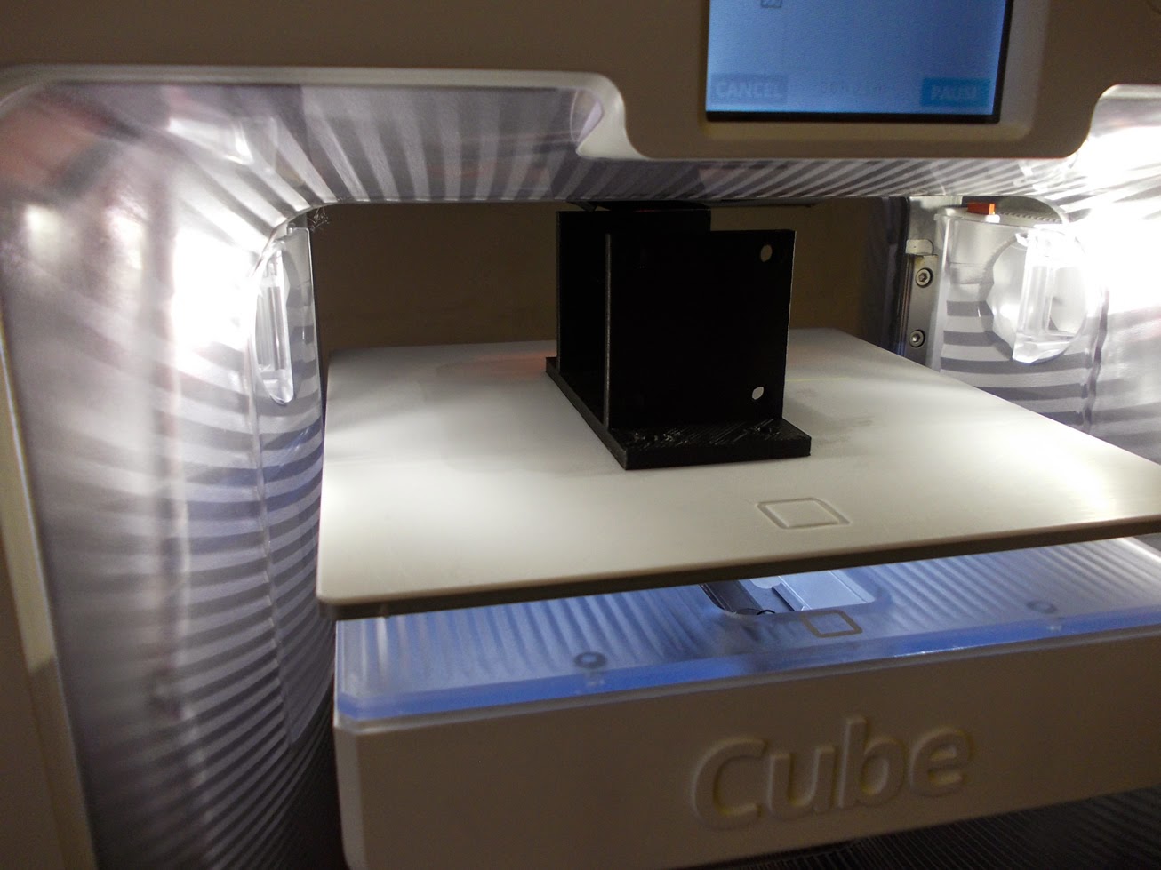
Note the lack of hole in the centre of the front mount. Whoops. We later drilled a hole using a pillar drill.

Leave a comment